The Science Behind Flexplates With Goerend Transmission
The highly engineered drivetrain component that must strike the perfect balance between strength and flexibility—while also absorbing rotational torque and axial thrust.
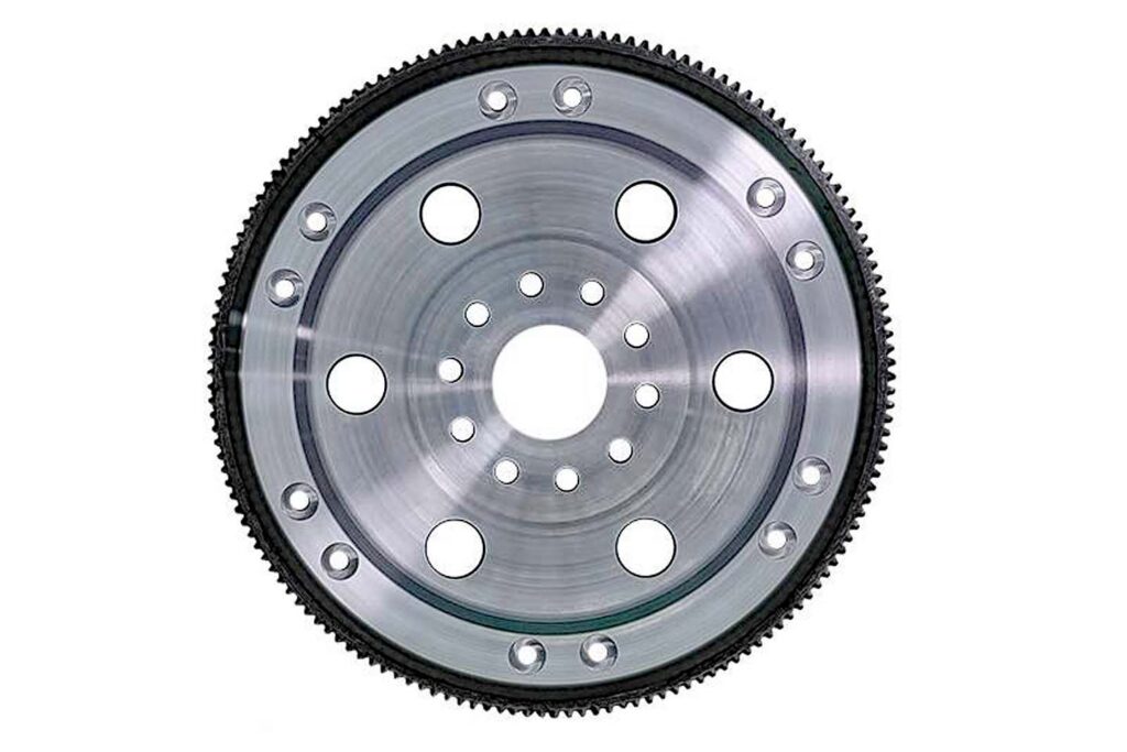
The flexplate is a critical but often misunderstood component in your truck. It acts as the mechanical link between the engine’s crankshaft and the torque converter. But while it may appear to be nothing more than a steel “plate,” the nature of its primary job within the drivetrain—to manage immense competing forces—makes its design far more complex than it seems.
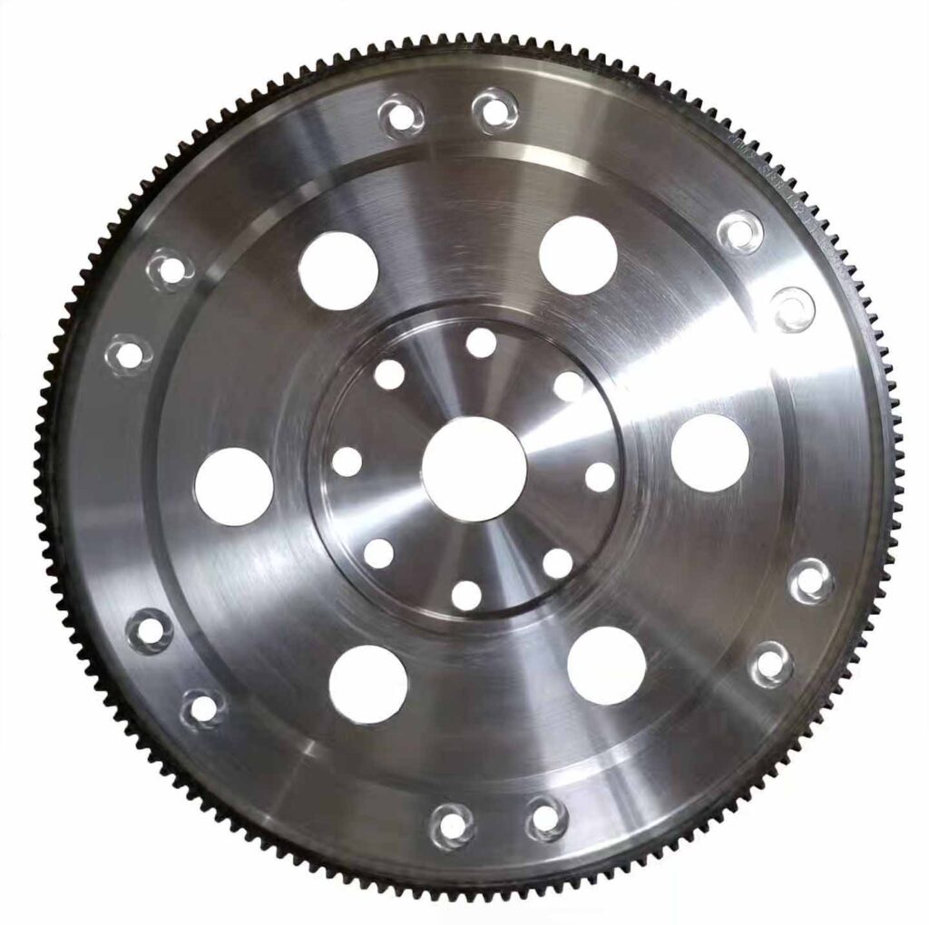
Essentially, the flexplate bolts directly to the rear of the crankshaft, with the crankshaft itself having almost no axial movement (typically only a few thousandths of an inch). In practical terms, the crankshaft can be considered fixed in the forward and backward direction. The torque converter then bolts to the flexplate and, because of its internal geometry, constantly applies a forward thrust force toward the engine. Since the crankshaft cannot move to absorb this force, the flexplate becomes the component that has to. In fact, it’s even designed to deform in order to accommodate this force.
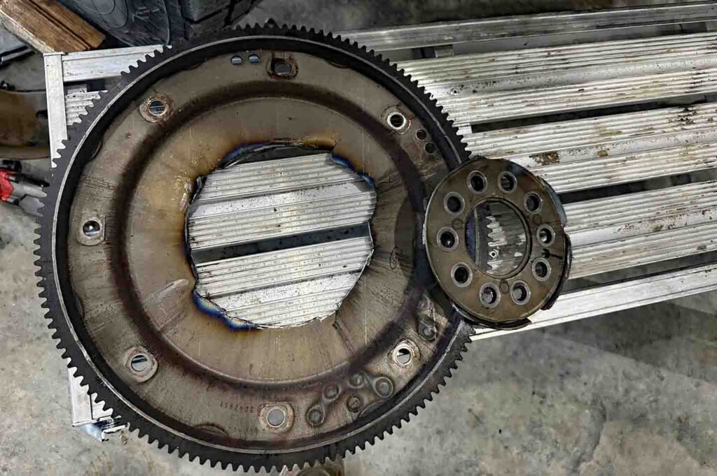
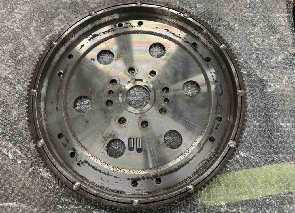
This creates a fundamental design challenge. The flexplate must be flexible enough to absorb thrust loads and cyclical deflection, yet strong enough to reliably transmit rotational torque from the engine to the transmission. Every time the driver applies or releases the throttle, internal pressures within the transmission change, causing the converter to push and release against the flexplate. This results in constant flexing. Over time, this repeated motion creates fatigue, and cracks typically develop near the mounting area where movement is most restricted. Photo Courtesy Of Lee’s Diesel Repair.
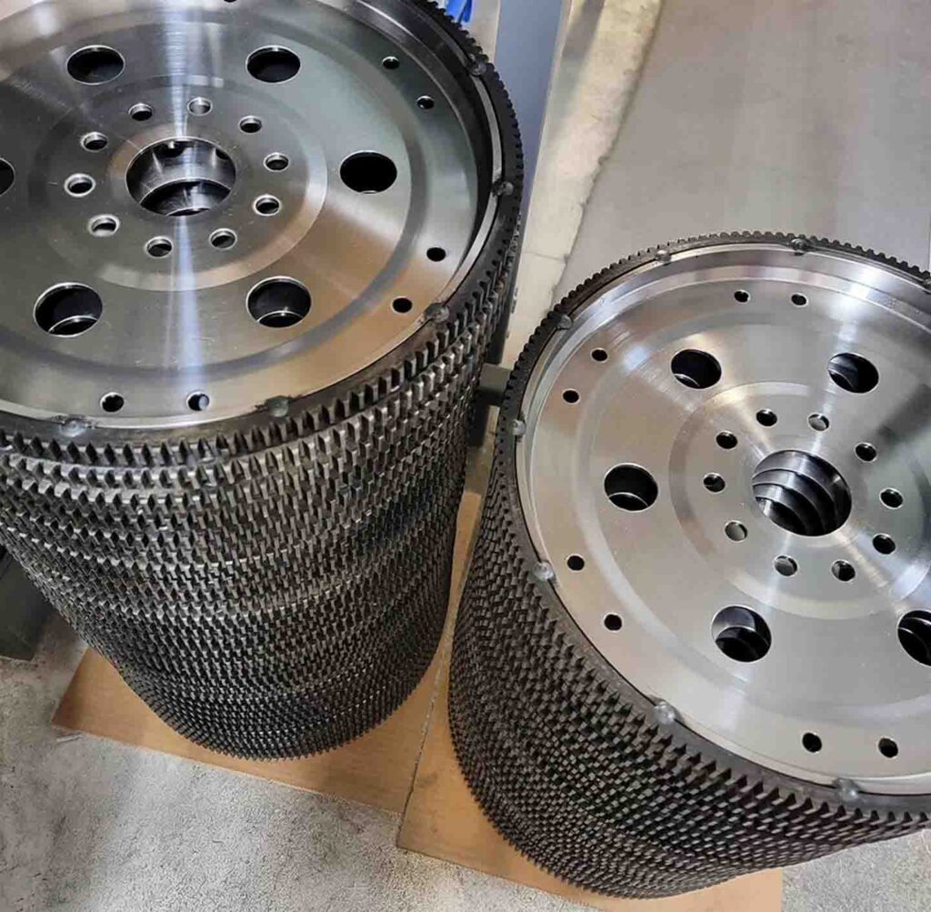
In addition to the forward and backward stresses it sees, the flexplate is subjected to significant rotational forces. As the engine spins, torque is transmitted through the plate to the converter. If the plate is too thin, it may flex easily under thrust loads but lack the structural integrity to handle torsional stress—leading to failure from rotational fatigue. On the other hand, if the plate is made thicker in an effort to improve torque capacity, it resists bending and instead concentrates stress in localized areas—again leading to cracking. This balance between flexibility and strength is the central engineering tradeoff in flexplate design.
The problem is further compounded by the fact that flexing introduces angular misalignment. When the plate deflects, the connection between the crankshaft and converter is no longer perfectly straight. This creates additional stress, as loads are now applied at an angle rather than along a direct axis. It’s similar to a person lifting a weight straight upward versus lifting it at an angle. Angled loading introduces significantly more strain on the system. As a result, the flexplate experiences not only axial and torsional forces, but also bending and misalignment stresses simultaneously.
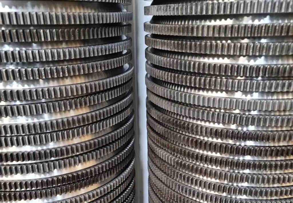
Material choice plays a key role in how well a flexplate can handle these conditions. Traditional flexplates made from lower-strength steels may fail at relatively low stress levels, while higher-strength alloys such as 4140 steel can withstand significantly greater loads before deforming or cracking. The internal structure of the material matters as well; cast materials tend to have less uniform grain structure compared to forged or billet-steel, making them more prone to failure under repeated stress cycles. For high-performance or racing applications, stronger materials are often required to meet safety standards as well as prevent catastrophic failure.
Another important concept is that the flexplate can act as a mechanical “fuse” in the system. In some cases, it is preferable for the flexplate to fail rather than transfer excessive force into the crankshaft and its thrust bearings. If the plate is made too rigid, it may protect itself from damage but instead cause wear or failure in more critical (and expensive) engine components. This highlights the importance of designing the flexplate not just for durability, but for controlled behavior within the overall system.
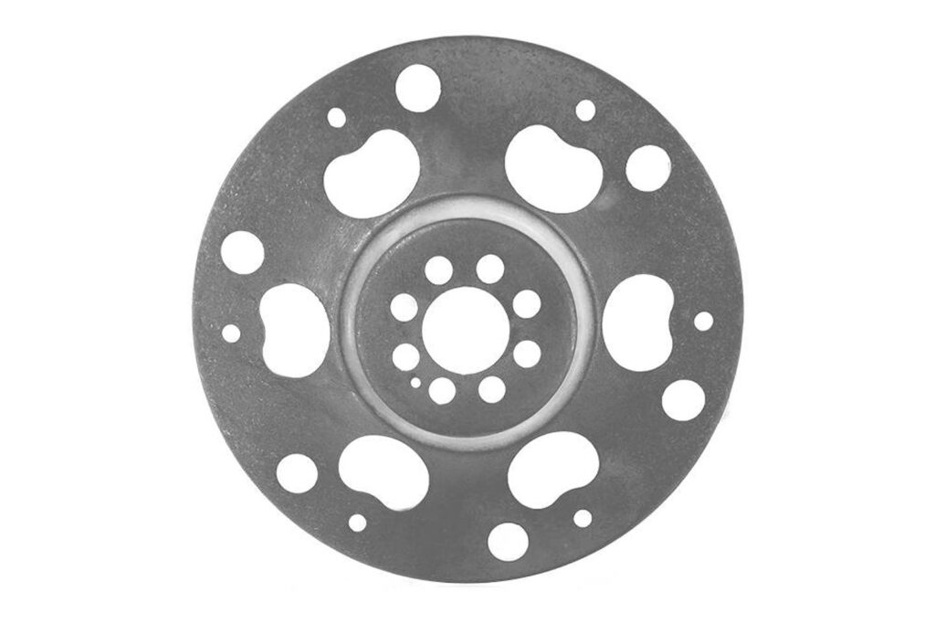
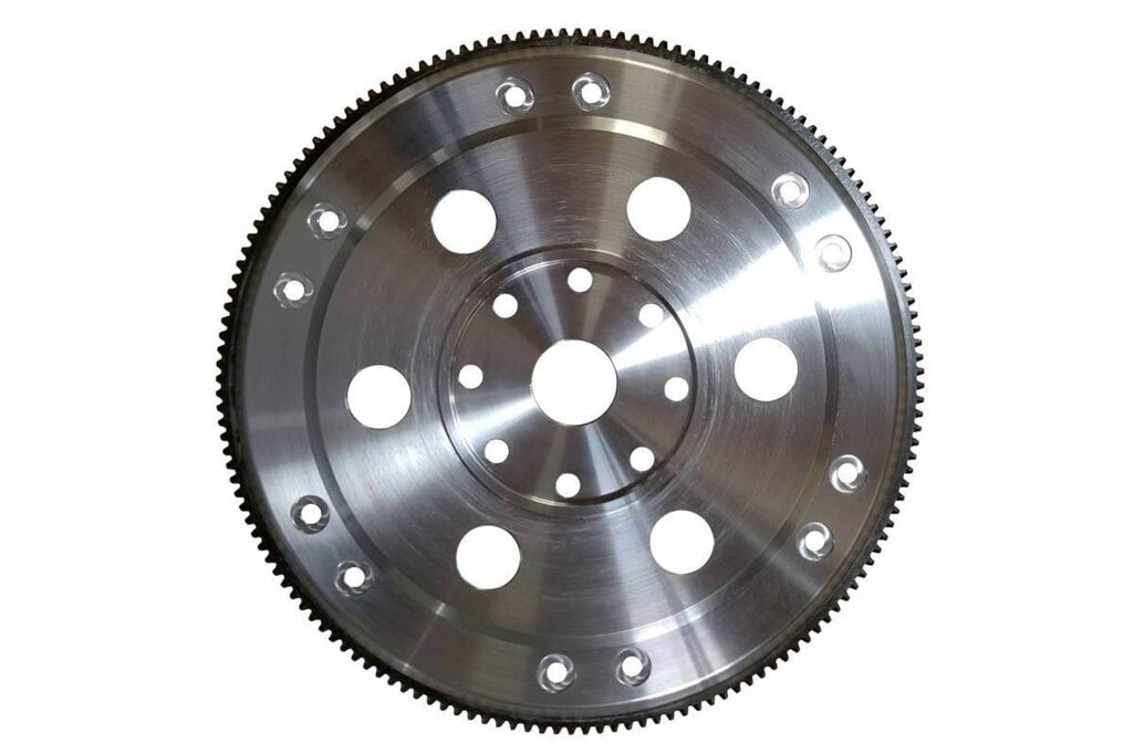
Design features such as holes or slots also influence how stress is distributed across the plate. Round holes tend to spread stress more evenly, reducing localized concentrations. On the other hand, slots may allow for increased flexibility, but can create areas where stress becomes focused. Engineers must carefully evaluate these features, often using simulation tools to determine how the plate will behave in real-world conditions. Additionally, processes like shot-peening can be employed to introduce compressive stress into the surface of the material, improving fatigue resistance and helping prevent cracks from developing.
Ultimately, the flexplate exists in a constant state of compromise. It must flex, but not too much. It must be strong, but not so rigid that it transfers damage elsewhere. It must handle both rotational torque and axial thrust while enduring continuous cycling over the life of the vehicle. Understanding these competing demands is key to designing a flexplate that performs reliably in both everyday driving and high-performance conditions.
Written by Mason Goerend